Why military aircraft, shipboard systems, and aerospace platforms operate at 400 Hz instead of 50/60 Hz — and how this frequency choice drives transformer design, weight savings, and system architecture.
In most of the world, electrical power is generated and distributed at either 50 Hz or 60 Hz. These frequencies were standardized in the early 20th century as a practical compromise between generator design, transmission efficiency, and the performance of motors and transformers at the time. For ground-based infrastructure — factories, homes, data centres — these frequencies remain perfectly adequate.
But in environments where weight and volume are at a premium — military aircraft, naval vessels, spacecraft, and ground support equipment — a different frequency standard has dominated for over seven decades: 400 Hz.
Why 400 Hz? The Physics of Frequency and Core Size
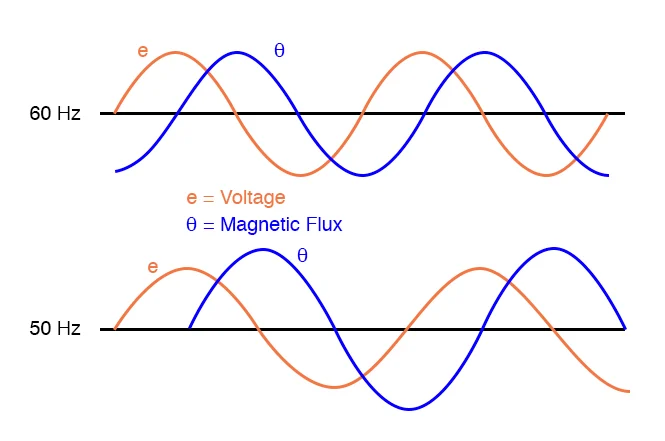
The relationship between operating frequency and transformer core size is governed by Faraday’s law of electromagnetic induction. The induced voltage in a transformer winding is proportional to the rate of change of magnetic flux, which in turn is proportional to the frequency of the applied voltage.
- 1At higher frequencies, the same voltage can be induced with a smaller core cross-section. A transformer designed for 400 Hz requires roughly 1/8th the core volume of an equivalent 50 Hz transformer for the same VA rating.
- 2This translates directly to dramatic weight and volume reductions — the primary reason military and aerospace systems adopted 400 Hz power distribution.
- 3For aircraft like the Su-30MKI or Tejas LCA, every kilogram saved in the power distribution system translates to increased fuel capacity, payload, or range.
- 4The same principle applies to naval vessels, where dense electrical systems must fit within tight hull compartments.
Historical Context: How 400 Hz Became the Standard
- 1During World War II, aircraft designers recognized that lighter electrical systems would directly improve flight performance. The 400 Hz standard emerged as the optimal trade-off between core size reduction and the practical limits of generator and motor design.
- 2By the 1950s, 400 Hz was formally standardized for military aircraft power systems through MIL-STD-704 (US) and equivalent NATO standards.
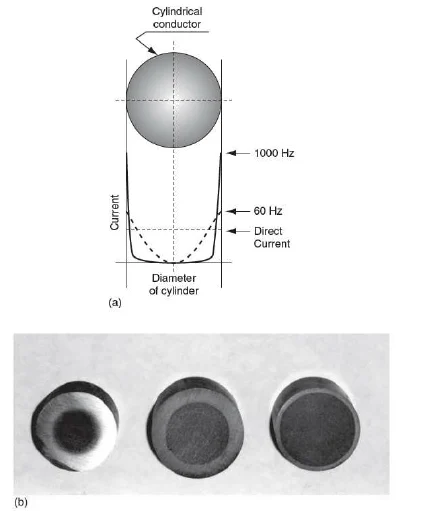
- 3The frequency was high enough to dramatically reduce transformer and motor size, but low enough to avoid excessive skin-effect losses in standard copper conductors.
- 4Today, 400 Hz remains the primary power frequency for military aircraft (fixed-wing and rotary), shipboard systems, spacecraft power buses, and airport ground power units (GPU).
Transformer Design at 400 Hz: Key Engineering Differences
Designing transformers for 400 Hz is not simply a matter of scaling down a 50 Hz design. Several engineering parameters change significantly.
- 1Core Material: Standard CRGO silicon steel is adequate for most 400 Hz applications, but at higher power levels, nanocrystalline or amorphous alloy cores may be specified to minimize core losses that increase with frequency.
- 2Winding Design: At 400 Hz, skin effect becomes more significant. Litz wire or thinner-gauge conductors may be required to maintain efficient current distribution across the conductor cross-section.
- 3Insulation System: Higher frequency operation can increase dielectric stress. Insulation systems must be rated for the higher dV/dt and potential partial discharge at elevated frequencies.
- 4Thermal Management: While the core is smaller, the volumetric power density is higher. Careful thermal design — including potting compounds, heat sinks, or forced-air cooling — is essential to maintain temperature rise within specification.
- 5Regulation and Leakage Reactance: Leakage reactance is proportional to frequency. At 400 Hz, regulation performance must be carefully controlled through winding geometry and interleaving techniques.
Ground Support Equipment: Bringing 400 Hz to the Tarmac
- 1Military and commercial aircraft require external 400 Hz power while parked on the ground — for avionics checkout, environmental control, and pre-flight system tests.
- 2Ground Power Units (GPUs) convert local 50/60 Hz mains power to 400 Hz using static frequency converters or motor-generator sets.
- 3The transformers inside these GPUs must handle the conversion efficiently while maintaining tight voltage regulation under varying aircraft loads.
- 4ETCC manufactures 400 Hz toroidal transformers for defence ground support applications, matching the mechanical and electrical specifications required by platform-specific technical documentation.
Economic Considerations: Weight vs. Cost
- 1400 Hz transformers are more expensive per unit than equivalent 50 Hz designs due to tighter tolerances, specialized core materials, and the lower production volumes typical of defence procurement.
- 2However, in aerospace applications, weight savings translate directly to operational cost reductions. A kilogram saved on an aircraft platform can be worth thousands of dollars over the aircraft’s operational lifetime in fuel savings alone.
- 3For naval applications, the smaller volume of 400 Hz equipment enables denser equipment layouts within fixed hull volumes — a critical advantage in modern warship design.
- 4The total cost of ownership calculation must therefore include system-level benefits (weight, volume, cooling requirements) rather than component-level unit cost alone.
ETCC’s 400 Hz Capability
ETCC has been manufacturing 400 Hz toroidal transformers for Indian defence programmes since the mid-1990s. Our 400 Hz production covers custom toroidal transformers for airborne electronics (Su-30MKI, Tejas LCA platform documentation), ground support equipment transformers for air base maintenance facilities, and shipboard power conversion transformers for naval electronic systems. Each unit is individually tested for ratio accuracy, insulation integrity, and temperature rise under rated 400 Hz excitation — not sampled, not extrapolated from 50 Hz test data.