Understanding the critical difference between metering and protection current transformers — accuracy classes, saturation behavior, core materials, and how to specify the right CT for your application.
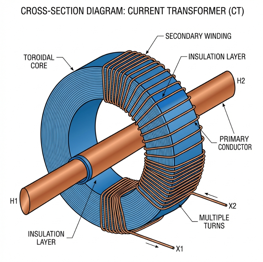
In power system engineering, current transformers (CTs) serve as the vital "eyes" of the installation, stepping down high primary currents to standardized levels for monitoring and safety.
However, a common engineering pitfall is assuming that a CT optimized for high-precision billing can also handle the rigors of fault protection. Specifying the incorrect accuracy class for your application can lead to significant revenue loss through measurement errors or, in the worst case, catastrophic equipment failure due to delayed relay tripping. Understanding the divergence between metering and protection topologies is essential for ensuring both financial precision and system reliability.
What is a Metering CT?
Metering current transformers are specifically engineered to provide extreme precision during the normal operating range of a circuit. Their primary function is to feed instruments like ammeters, energy meters, and wattmeters that require highly accurate data for billing and load monitoring.
- 1Precision at Normal Loads: Metering CTs are designed to maintain a linear response within 5% to 120% of the rated primary current. For a Class 0.5 rating, this means the ratio error cannot exceed ±0.5% at the rated current.
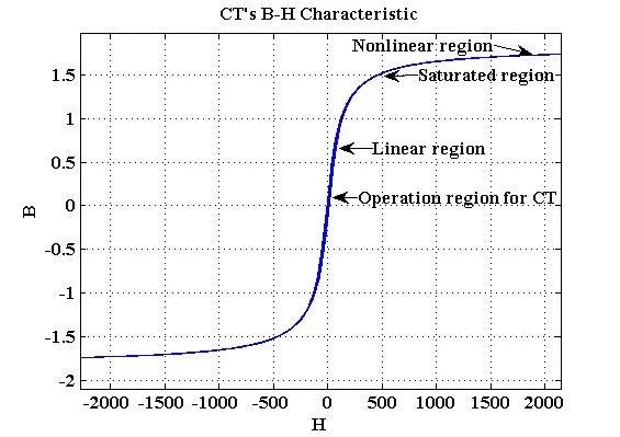
- 2Instrument Protection via Saturation: A unique "safety" feature of metering CTs is their intentional saturation characteristic. These units are built with high-permeability cores (often using nickel-iron or nanocrystalline materials) that saturate at relatively low overcurrents, typically 2–5× the rated current. This protects delicate and expensive metering equipment by "clipping" the secondary output during a massive fault.
- 3Practical Application of Class 0.5: Class 0.5 is the industrial standard for commercial and industrial billing. For critical revenue-grade metering where even a 0.3% discrepancy could translate to massive annual losses, specialized "S" classes like 0.2S or 0.5S are used, as they extend high accuracy down to 1% of the rated current.
What is a Protection CT?
While a metering CT is a "precision scale," a protection CT is a "critical alarm." Protection CTs must maintain their performance during extreme electrical disturbances, such as short circuits, to provide a faithful signal to protective relays.
- 1Fault Current Performance: Unlike metering units, protection CTs must not saturate during a fault. They are designed with larger cross-sectional cores made of high-saturation grain-oriented silicon steel (GOSS) to handle flux levels up to 10–30× the rated current.
- 2Decoding Class 5P10 and 10P20: Protection classes use a specific notation. In a "5P20" rating, the "5" represents a maximum composite error of 5%, the "P" stands for Protection, and the "20" is the Accuracy Limit Factor (ALF). This means the CT is guaranteed to stay within 5% accuracy even at 20× the rated current.
- 3Class 1.0 Use Cases: While Class 1.0 is technically a metering grade, it is frequently used for general measurement and backup protection. It offers a balance of cost and accuracy (±1%) for non-critical monitoring and overcurrent relays where extreme precision is secondary to reliability.
Navigating the Standards: IEC 61869-2 and IS 2705
To ensure global interoperability and safety, CT classifications are strictly governed by international and regional standards.
- 1IEC 61869-2: This is the current international standard (replacing the older IEC 60044-1) that defines the limits for ratio error, phase displacement, and composite error.
- 2IS 2705: In India, CTs are manufactured and tested according to IS 2705. Part 2 specifically covers measuring CTs, while Part 3 focuses on protective CTs. Compliance with these standards ensures that the CT can withstand the thermal and mechanical stresses of short circuits as defined by the rated short-time thermal current.
How to Choose the Right Accuracy Class
Selecting the correct CT involves more than matching the primary current. Engineers must evaluate the total system burden and the expected fault levels.
| Feature | Metering CT | Protection CT |
|---|---|---|
| Accuracy Range | 5% to 120% of rated current | Up to 10× or 20× rated current (ALF) |
| Saturation | Early saturation to protect instruments | High saturation threshold for fault detection |
| Common Classes | 0.2, 0.5, 1.0 | 5P, 10P, PX |
| Internal Core | Nickel-Iron or Nanocrystalline | Cold-Rolled Silicon Steel (CRGO) |
Engineer’s Selection Checklist
- 1Define the Purpose: Is it for billing (Metering) or relaying (Protection)?
- 2Verify the Rated Burden: Calculate the total VA of the connected device and cable leads. If the load exceeds the CT's rated burden (e.g., 15VA), accuracy will drop.
- 3Calculate the Required ALF: For protection, the ALF must be greater than the ratio of the maximum fault current to the rated primary current (ALF ≥ I_fault / I_rated).
- 4Check for "S" Requirements: If your load fluctuates significantly, specify 0.2S or 0.5S to ensure accurate billing at low currents.