Side-by-side comparison of toroidal and EI laminated transformers: core loss, EMI, weight, noise, efficiency, and cost. Includes spec tables and decision matrix from a manufacturer winding both types since 1994.
Quick Comparison: Toroidal vs EI Transformer
| Parameter | Toroidal Transformer | EI Transformer |
|---|---|---|
| Efficiency | 95–98% | 85–90% |
| Weight (same VA) | Up to 50% lighter | Baseline |
| Volume | 40–64% smaller | Baseline |
| EMI / Stray Field | 90–95% lower | Higher (air gap leakage) |
| Acoustic Noise | ~8× quieter | Audible hum common |
| Standby Power | ~1/16th of EI | Higher no-load losses |
| Unit Cost | Higher (complex winding) | Lower (automated stamping) |
The fundamental challenge in modern power electronics is the relentless engineering battle to maximize power throughput while simultaneously minimizing the spatial footprint and total mass of the system. At the heart of this struggle lies the magnetic component — the transformer.
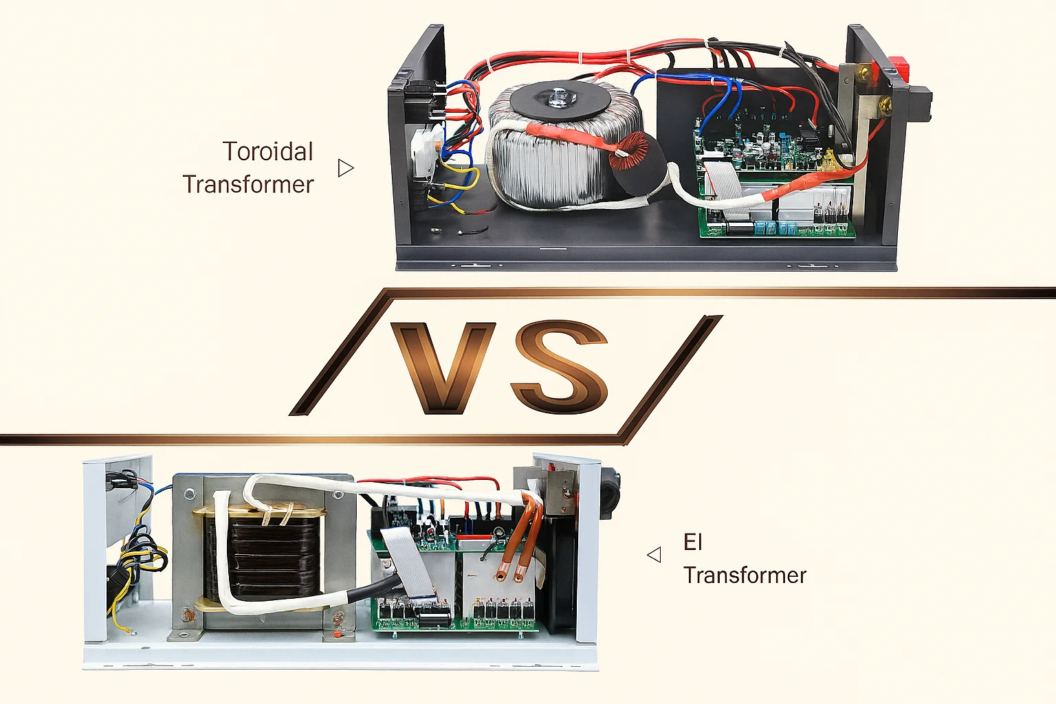
In the landscape of power supply design, two foundational geometries have emerged as the primary contenders for low-to-medium power applications: the toroidal transformer and the E-I (laminated) transformer. While both devices operate on the same core principles of Faraday's Law of Induction, their structural differences lead to radically different operational signatures.
The EI transformer, characterized by its stacked rectangular sheets, has long served as the industrial workhorse due to its cost-effectiveness and ease of assembly. However, as requirements for high efficiency, electromagnetic compatibility (EMC), and acoustic silence become more stringent, the toroidal transformer — with its seamless ring-shaped core — has positioned itself as the premium specialist for noise-sensitive and space-constrained applications.
Core Construction: The Physical and Metallurgical Differences
The primary differentiator between these technologies is the physical architecture of the magnetic circuit.
- 1An EI core is constructed from individual silicon steel laminations stamped into the shapes of the letters "E" and "I".
- 2These pieces are stacked alternately to form a rectangular frame with a center leg, around which the copper windings are placed on a pre-wound bobbin.
- 3This modular approach is inherently convenient for high-speed automated production but introduces several magnetic compromises.
- 4In stark contrast, a toroidal core is manufactured by winding a continuous strip of grain-oriented silicon steel (GOSS) under tension into a tight, seamless ring or "donut" shape.
The Physics of Air Gaps and Reluctance
The performance of any magnetic core is dictated by its total reluctance — the magnetic equivalent of electrical resistance.
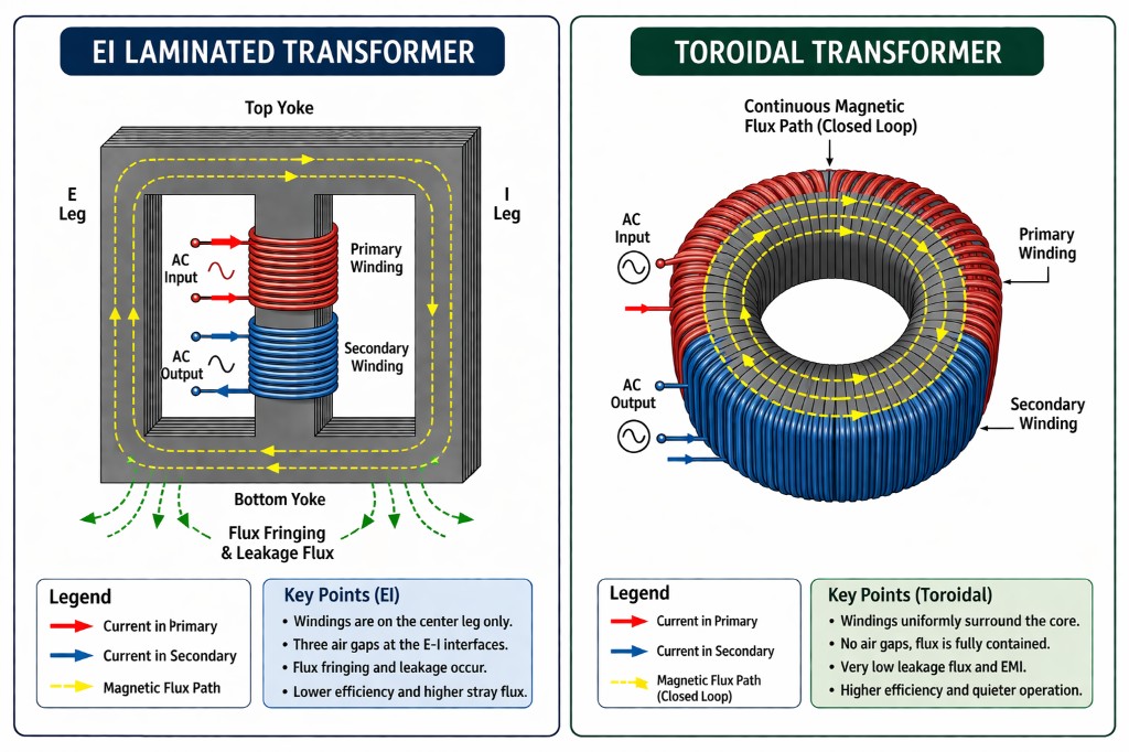
- 1In a traditional EI transformer, the interface where the "E" and "I" segments meet creates three distinct physical gaps in the magnetic path.
- 2Even with precision stacking and clamping, these microscopic air gaps represent areas of high reluctance. According to the fundamental relationship Φ = F/R, higher reluctance means less flux for the same magnetomotive force.
- 3These gaps are the primary sites of "flux fringing," where magnetic field lines exit the core and radiate into the surrounding environment as leakage flux.
- 4A toroidal transformer eliminates this problem entirely. Because the core is wound from a single, continuous ribbon of steel, there are no air gaps or discontinuities in the magnetic path.
- 5This "closed-loop" geometry ensures that the magnetic flux is trapped within the core, allowing for nearly ideal coupling between the primary and secondary windings.
Grain Orientation and Material Utilization
The metallurgy of the core material also plays a decisive role in efficiency.
- 1Silicon steel is "grain-oriented," meaning its magnetic properties are optimized in the direction of the rolling process. In a toroidal core, the flux path is perfectly aligned with the grain of the steel throughout the entire 360-degree circuit.
- 2In an EI core, the rectangular geometry forces the flux to travel against the grain orientation in several sections, specifically at the corners and the junctions between the "E" and "I" segments.
- 3This misalignment leads to increased hysteresis losses and a lower saturation flux density.
- 4Toroidal transformers are typically designed to operate at flux densities of 1.6 to 1.8 Tesla (16 to 18 kilogauss), whereas EI transformers are generally limited to 1.2 to 1.4 Tesla to avoid excessive core losses.
Winding Topology and Surface Area
- 1EI Transformer: Primary and secondary windings are placed only on the center leg of the E-core. This leaves roughly 66–70% of the core exposed, causing uneven heat distribution and allowing more magnetic flux leakage.
- 2Toroidal Transformer: Uses uniform 360° windings that completely surround the core. The full winding coverage confines the magnetic field, reducing leakage flux.
- 3Heat spreads across the entire core surface in a toroidal design, improving cooling, efficiency, and reliability.
Analysis of Core and Copper Losses
- 1Total transformer loss = Core loss (iron loss) + Copper loss.
- 2Core losses mainly include hysteresis loss (energy needed to realign magnetic domains) and eddy current loss (circulating currents induced inside the core material).
- 3Toroidal cores reduce hysteresis due to better grain alignment and no air gaps. Their continuous ribbon core structure also reduces eddy currents compared to stacked EI laminations.
- 4Because of this, toroidal transformers typically reach 95–98% efficiency, while EI transformers are usually below approximately 90%.
- 5Copper loss depends on wire resistance. Toroidal transformers have a shorter mean length of turn (MLT), meaning less wire is needed — shorter wire → lower resistance (R = ρL/A) → higher efficiency.
Volumetric Efficiency and Weight Reduction
- 1Toroidal transformers have a smaller footprint because they operate at higher magnetic flux density with lower losses.
- 2For the same power rating (VA): up to 50% lighter and 40–64% smaller in volume than EI transformers.
- 3Smaller size reduces product weight, chassis requirements, and shipping costs.
- 4Ideal for space-constrained devices like audio amplifiers, servers, and portable medical equipment.
Quiescent Power (Standby Power)
- 1Quiescent power is the energy consumed when the transformer is powered but not supplying load.
- 2Due to higher magnetic efficiency, toroidal transformers require much less excitation energy.
- 3They typically consume approximately 1/16th of the standby power of comparable EI transformers.
- 4This results in significant energy savings in systems that stay on for long periods.
Electromagnetic Interference (EMI)
- 1Transformers can generate electromagnetic interference (EMI) and acoustic noise.
- 2EI transformers have air gaps and uneven windings, causing higher stray magnetic fields.
- 3Toroidal transformers have a closed magnetic path and symmetric winding, reducing leakage.
- 4External magnetic field can be 90–95% lower than EI transformers.
- 5Often eliminates the need for extra magnetic shielding, reducing design complexity and cost.
Acoustic Hum and Magnetostriction
- 1Transformer hum is mainly caused by magnetostriction and vibration of laminations.
- 2EI cores consist of stacked plates that can vibrate and loosen over time, producing audible noise.
- 3Toroidal cores are a single tightly wound structure, often epoxy-impregnated.
- 4They have no air gaps and minimal vibration, resulting in about 8× lower audible noise.
Technical Trade-offs
Inrush Current
- 1Toroidal transformers can experience very high inrush current when powered on.
- 2Because of high magnetic efficiency and residual magnetism, the core may momentarily saturate at startup.
- 3Inrush current can reach 10–40× the rated current.
- 4Designers often add NTC thermistors or soft-start circuits to limit this surge.
- 5EI transformers are less sensitive to inrush due to their inherent air gaps.
Mounting Considerations
- 1EI transformers are easy to mount using brackets or corner bolts.
- 2Toroidal transformers typically use a single center bolt with rubber pads.
- 3Mounting hardware must not form a conductive loop, which could act like a shorted secondary turn and cause overheating.
- 4For harsh environments, toroids may be resin-potted or encapsulated to improve durability and simplify assembly.
Economic Analysis: Initial Cost vs Total Cost of Ownership
- 1EI transformers are cheaper initially because their manufacturing process (lamination stamping and bobbin winding) is highly automated and inexpensive.
- 2Toroidal transformers cost more due to the complex winding process (wire must pass through the core), specialized winding machines and skilled labor, and use of higher-grade grain-oriented silicon steel (GOSS).
However, when considering Total Cost of Ownership (TCO), toroidal transformers can be more economical because they reduce system-level costs:
- 1Chassis savings: Smaller size can allow smaller and cheaper enclosures.
- 2Shielding savings: Very low EMI, often eliminating the need for additional magnetic shielding.
- 3Cooling savings: Higher efficiency means less heat, sometimes removing the need for cooling fans.
- 4Energy savings: Lower standby and core losses can reduce electricity consumption over years of operation.